By Aangan Editorial · Published 21 October 2026 · P01.1 concept
A 2.95 × 5.20 m kitchen uses counters arranged around a clear utility route, a southern window and a separate utility connection. Inspect the fittings, dimensions and movement before entering its matching 3D view.
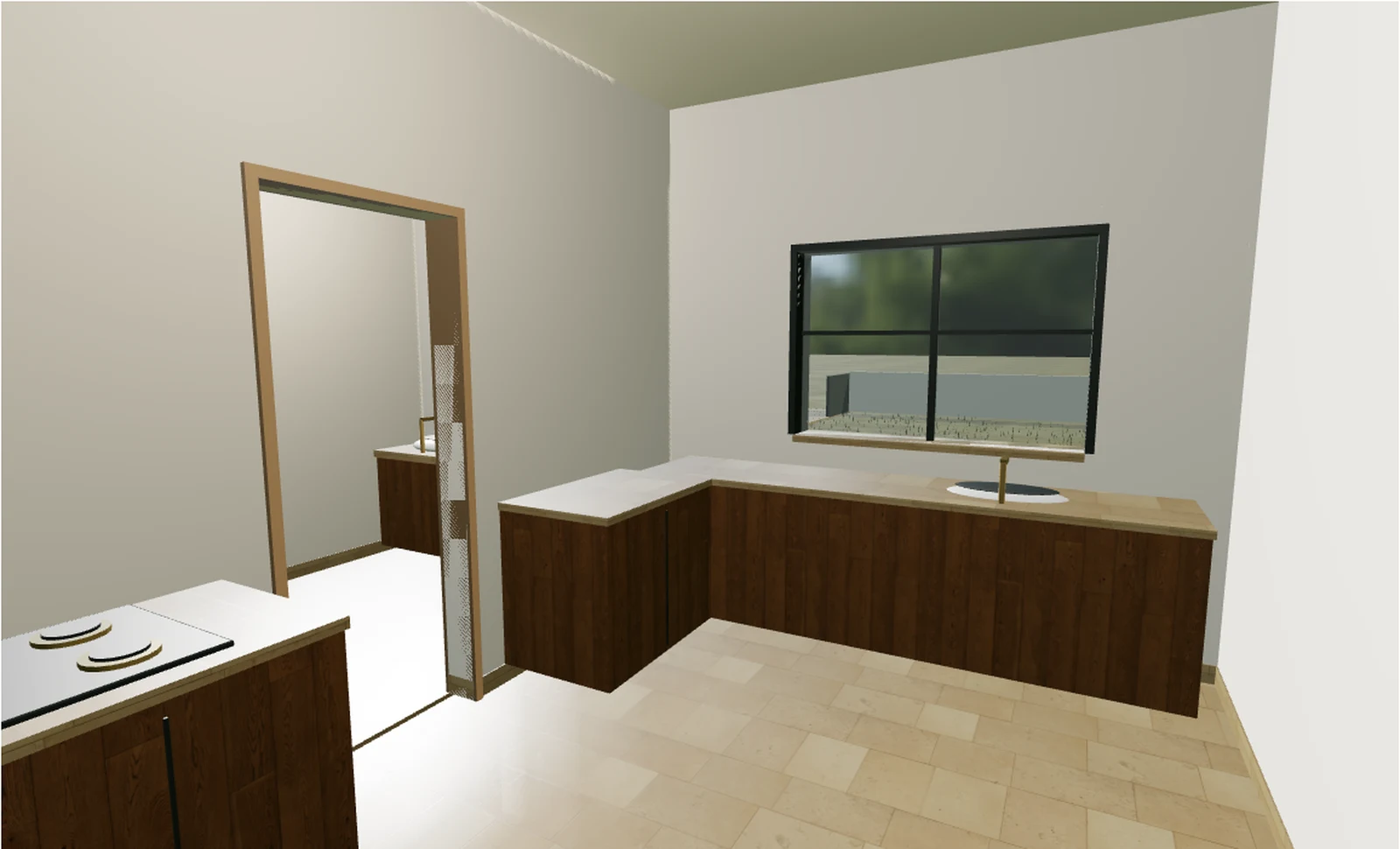
Explore without signing in. Sign in to create and save a private copy.
Read the kitchen in its whole-house context
Door D08 connects the kitchen to the hall; D10 connects it to the utility room. The living and dining room is reached through the hall rather than through a direct opening in the shared wall. That relationship matters when carrying meals and returning dishes.
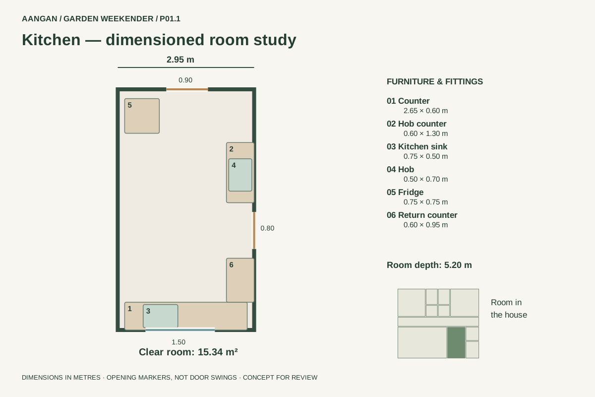
The clear kitchen measures 2.95 × 5.20 m, or 15.34 m² rounded to two decimals. The utility is a separate room and is excluded from this figure. This is the existing P01.1 concept, not a kitchen fitted into an assumed generic farmhouse.
Keep the utility doorway clear
The southern counter is scheduled at 2.65 × 0.60 m, while the eastern hob counter is 0.60 × 1.30 m. The sink occupies a 0.75 × 0.50 m footprint on the southern run. A 0.50 × 0.70 m hob footprint sits on the eastern run. A separate 0.60 × 0.95 m return joins the southern counter beyond the utility doorway. P01.1 corrects the former continuous run that crossed D10, leaving a 1.20 m gap between counter segments around its 0.80 m opening. The hob has moved along the shorter northern run.
A 0.75 × 0.75 m fridge footprint sits near the northern end. There is no island in this plan. Leaving the centre open is a deliberate feature of this example, but the arrangement still needs checks against actual appliances, open doors, worktop details and the users’ needs.
Coordinate the window and services
W09 is the southern kitchen window: 1.50 m wide, with a 1.05 m sill and a 1.05 m opening height. It sits above the counter zone. The rendered scene uses a pale stone-like work surface, timber-tone cabinetry and a light floor, continuing the house’s warm material palette.
The model does not resolve a ventilation design, extraction duct route, appliance installation instructions or a coordinated electrical and plumbing layout. The presence of a window or a hob in a render is not evidence that those systems have been designed.
Follow food, people and dishes
The room viewpoint starts near the northern end and looks toward the counter corner. Compare the position of the fridge, sink, hob and utility doorway with the drawing. Then move into the hall to understand the route to dining; this gives a more useful picture than an isolated kitchen image.
The still view comes from the public 3D scene. Cabinet fronts and surface materials are illustrative. They help communicate the concept but do not specify joinery construction, hardware, stone thickness, appliance brands or installation tolerances.
Develop the practical brief
Record how groceries arrive, how many people cook together, which appliances you use and where bulky serving items should live. Ask for cabinet elevations, an appliance list and coordinated services before seeking an installation quote. A supplier’s proposal should use the same dimensions and agreed scope.
Customise a private copy of the house to explore room relationships. For a more detailed kitchen brief, use the linked kitchen planning guide. Changes to openings, structure or service positions require appropriate professional assessment for the actual property.